


Since 2016, U.S. Ordnance has been the sole supplier of the US Model MK19 Mod 3 and Mod 4 machine guns to U.S. military and OGA end users. In 2022, they were issued the NSN as sole supplier, with an IDIQ contract of up to $50 million. As we go to press, they are in first article testing on the contract, and we were allowed to participate in the testing, phase I. (Phase II will be reported on in the first issue of SADJ 2024, it’s an extensive live firing test).
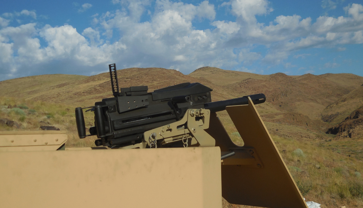
MK19 Mod 3
Specifications
- Caliber: 40x53mm
- Weight: 77.6 lb. (35.2kg) empty
- Length: 43.1 in. (1090mm)
- Width: 9.46 in. (240.4mm)
- Barrel Length: 16.25 in. (413mm) (Removable)
- Muzzle Velocity: 750-790 fps (230-240 m/s)
- Effective Firing Range: 1,500m (1,600 yards)
- Maximum Firing Range: 2,212m (2,419 yards)
- Feed system: either 32 or 48 grenade belts in metal can, M16A2 link.
Since U.S. Ordnance received the NSN and contract, there are now over 186 parts inspections that must be accomplished. Each one must meet the military standards for production. There is also a protocol testing called for in MIL-G-70790 (AR), the Military Specification for Gun, Machine, 40mm MK19 Mod 3, which must be strictly adhered to and passed with government inspectors viewing the proceedings. In this article, we’ll review relevant first parts of the testing we observed.


Section 3.7 Marking: Each machine gun and each part for which marking is prescribed shall be clearly marked in accordance with MIL-STD-130. Each receiver shall be identified with a serial number which shall be assigned by the procuring activity. The markings in this photo are the correct ones according to the MIL-STD. The barrel markings are as well, but parts like the barrel also receive a “PM” mark for “Proof” and “Magnetic Particle Tested” (See the M249 article in this issue for Magnaflux procedures).


Finished MK19 barrels waiting for assembly. As part of the MIL-STD, the grooves must be checked for height all through samples of the production barrels. Here, an extremely thin shim is cut cross-sectionally of the middle of the barrel, and the consistency and depth of grooves related to lands are checked, as well as finish depth. The cutaway barrel is for reference on the chamber and how the projectile is entering the grooves in the bore. Obviously, these are destructive tests and done on random barrels during the specification match testing.


In Section 4.5.8 Trunnion Load, a. for First Article Inspection, this test shall be performed concurrently with the belt pull test. B. Mount a Quartz Force Link Cell Kistler Model 9362 with a Charge Amplifier Model 504E and a Filter Model 545A (Or Equivalent) directly below the receiver, below the locking pin, integral with the mount and in alignment with the receiver buffers. C. Record a time -load trace of recoil using a Honeywell Visicorder Modl 1858 with a TCD (tape compatible differential) Amplifier Model 1887, or approved alternate equipment. D. Trunion load forces are to be measured at the mounting point. The last three (3) rounds of the belt fired shall be discounted. The mount shown here is a special mount custom made to the government specification for the test. The Kistler Force meter is a very expensive and sensitive piece of equipment, yet it is built to handle greater recoil forces than it will measure in this test. The reason for testing during the belt-pull test is based on finding variations in the side weight of the belt, and as the belt lightens the forces will change. This data will be valuable to see the consistency of the construction. After this first article test, the trunnion load tests will be less frequent but based purely on single rounds fired.

In the next issue of Small Arms Defense Journal, we will be joining U.S. Ordnance for the full-tilt firing part of the test. The ammo is lined up, the testing fixtures are ready, and we’ll be doing cadenced endurance testing, temperature testing, belt-pull, cyclic rate of fire, angle of fire, firing modes, accuracy, reliability, and a host of other tests. The full trunnion load test will be done several times through the testing. Be sure to join us!


