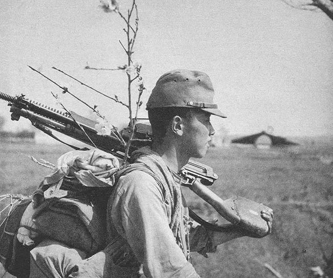
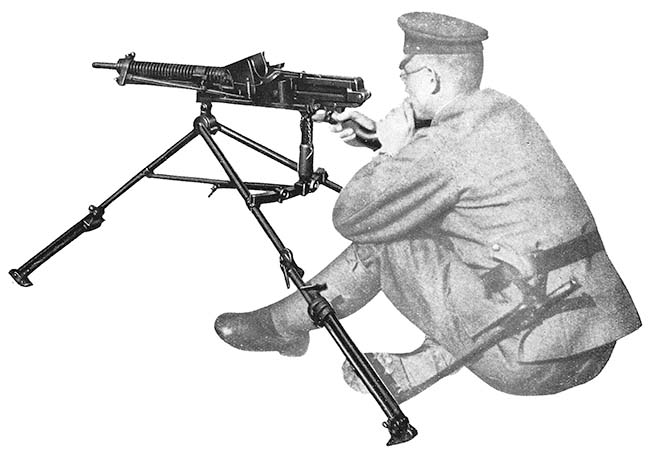
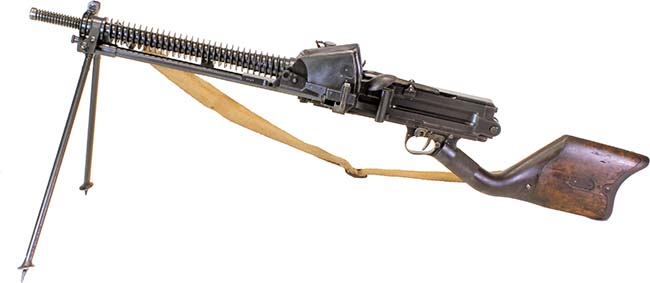
ABOVE: Right side view of the Type 11 LMG
In preparing research for this article it was found that there was no consistent consensus on the actual proper name of this weapon among the many sources utilized – both in English and in Japanese. A good part of that may be as simple as how the Japanese word or words were translated into English, the time period or era in which it is discussed or the emblematic usage of a nick-name. This gun is known by many names: Type 11, T-11, Taisho 11, Nambu Type 11, Nambu Taisho 11 and Model 1922; with Type 11 and Taisho 11 being the most encountered. For consistency purposes the name used throughout this article will be Type 11 as that is what it is commonly known as and accepted in the broadest of terms.
At the turn of the twentieth century, the Japanese military, like most of the rest of the world, was unsure of the effectiveness of machine guns and what they meant and how they were to be used on the battlefield, whether offensively or defensively and how they would, or would not, affect the outcome of engagements. They had no modern firearms strategies and relied on foreign designed guns to test, evaluate and use. The leading candidates of the time were the water-cooled short recoil Maxim gun and the air-cooled gas operated French Hotchkiss gun. The Japanese ultimately choose the Hotchkiss Model 1901 gun as they felt that even though the Hotchkiss used 24-round feed strips, being air cooled and lighter in weight provided them with a mobility advantage without the reliance of always being near a water source. Thus it was the combat knowledge gained in the Russo-Japanese war of 1904-1905 where the Japanese used the Hotchkiss Model 1901 heavy machine guns versus the Russian Maxims that convinced the Japanese of the usefulness of machine guns; particularly in providing covering fire for advancing infantry.
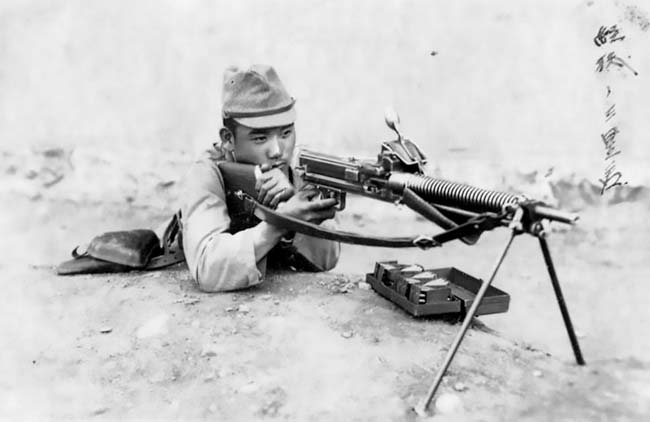
Later, as World War I raged all across Europe in 1914, Japanese military attachés made direct observations of the battles and combat tactics, which
ultimately reinforced their estimations of the use of automatic weapons in warfare. Wanting to expand its sphere of influence in the Far East, Japan sided with the Allies and declared war on Germany in August 1914, quickly occupying German-leased territories in China’s Shandong Province and the Mariana, Caroline and Marshall islands in the Pacific. While the rest of the world was focused on the European battleground, Japan continued to expand and consolidate its position in China and expanding control over German holdings in Manchuria and Inner Mongolia. World War I permitted Japan to expand its influence in Asia and its territorial holding in the Pacific while the Imperial Japanese Navy, seized Germany’s Micronesian colonies.
It was in 1914 that Japan started production, under license, of the Taisho 3 heavy machine gun based upon the design of the French Hotchkiss Model 1914 as their heavy machine gun in 6.5x50mm Arisaka ammunition. Beyond that, they recognized the value of a lightweight, man-portable weapon such as they saw with the Lewis gun as a huge advantage for infantry on the offensive. After the hostilities ended in Europe, the Japanese Army Technical Bureau was charged with the development of a lightweight machine gun that could be easily transported and used by one man in the infantry squad resulting in the Type 11 in 1922. Gaining combat experience in Japan’s growing sphere of influence in Manchuria and northern China confirmed Japan’s effectiveness of providing automatic covering fire for advancing infantry troops.
The first light machine gun to be manufactured in large quantities in Japan was the Type 11 light machine gun and when accepted was “Typed” in commemoration after the 11th year of the reign of Emperor Taisho, or 1922. The gun was a highly modified design by the famous Japanese arms designer General (then Colonel) Kijiro Nambu of the French Hotchkiss Mle 1909 light machine gun. Retaining the cooling fins on the barrel and the collapsible attached bipod, he instead of using the typical Hotchkiss feed strip design, developed a hopper feed housing design holding 30 rounds to feed the weapon. He also completely redesigned the bolt and locking system. His design also meant that the bolt violently extracted the spent cartridge casing requiring an oiler system to oil the cartridges prior to chambering. This oil reservoir had to be located immediately over the center of the feedway causing the sights to be offset to the right. He then radically changed the shoulder stock configuration to be offset to the right to be ergonomically beneficial because the sights were offset. The Type 11 saw active service in the Imperial Japanese Army from 1922 through to the end of World War II in 1945. It was the oldest Japanese light machine gun design to see service in the Pacific War in World War II even though it was superseded by the Type 96 light machine gun (6.5x50mm Arisaka) in 1936 and then the Type 99 light machine gun (7.7x58mm) in 1939. Both guns resembled the 1920’s design of the Czech ZB 26 being gas operated with a top feed magazine and bipod mount, but the Japanese guns were completely different internally.
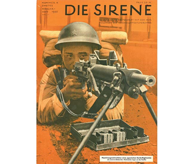
Type 11 (1922) 6.5mm Light Machine Gun
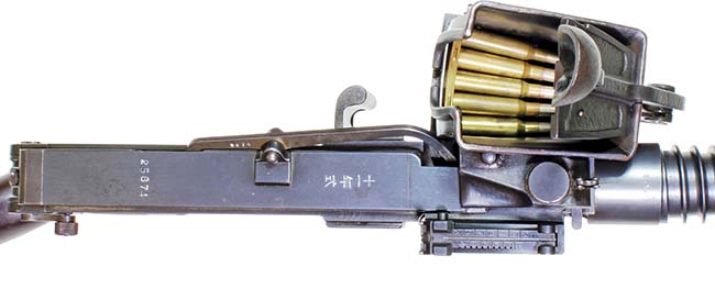
The Type 11 was the standard equipment in the Imperial Japanese Army infantry squad. It is gas-operated, air-cooled, and hopper fed and full automatic only. Like many Japanese automatic weapons, its design stems from the French Hotchkiss system, but the method of feed, consisting of a removable feed housing hopper attached to the left side of the receiver in line with the feedway and charged with clips of cartridges, is unique. The hopper holds six five-round clips; or thirty rounds in all. The five-round clips are stacked lying flat above the receiver, secured by a strong spring arm follower, and the rounds stripped from the lowest clip one at a time, with the empty clip thrown clear and the next clip automatically falling into place as the gun was fired.
The hopper can be refilled while attached and does not require removal during operation and can be replenished at any time. The inherent and obvious disadvantage of this hopper system was that the open feeder box was susceptible to dirt, dust, grime and mud entering the gun. That, along with poor dimensional tolerances, made the gun prone to operational jams. Additionally, it was practically impossible to reload the weapon during an assault charge due to the clip feeding system and the strong spring arm follower holding the cartridge strips in place. A soldier literally needed three hands to reload the weapon while advancing
Another issue was that the Type 11 had to use a reduced charge rifle cartridge as it would not function properly with the standard-charge rifle ammunition as it was causing reliability problems. This reduced-charge ammunition contains 2 grams of propellant instead of the 2.15 grams that is the standard charge for rifle ammunition. All reduced-charge ammunition cardboard boxes are marked with a Roman letter G inside a circle. The “G” was for the Japanese word “gensou” – or “reduced.” The ammunition is loaded in clips of 5, placed 1,440 rounds to the wooden box. Clips are also packed 3 clips (15 rounds) to a cardboard container and 24 clips (120 rounds) in a small steel ammunition case with a handle. Because the Type 11 had to use a reduced load, it of course negated the advantage of a single cartridge compatibility with their Type 38 rifle.
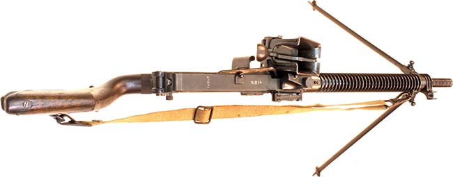
Another unique and easily identifiable aspect of the Type 11 is the ‘bent’ buttstock to the right. The trigger housing extends behind the trigger with a very narrow metal wrist that then expands into a wide wooden buttstock. This entire assembly is offset to the right. Since the cartridge oiler is located along the top of the receiver along the centerline axis, the sights have to be offset to the right. The idea being that the stock was also offset to the right to align with the offset sights. (Though offset sights are not unusual in guns designed with a magazine feed on the top of the receiver like a ZB or Bren gun, whose stocks are not offset, apparently in 1922, Colonel Nambu thought it mattered.) Another (weak) theory that surfaces on occasion hypothesized that due to the weight of thirty cartridges loaded in the hopper that hangs from the left side of the gun, to counteract that weight imbalance, the stock was offset to the right.
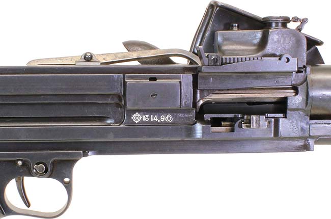
Overall, identifying the Type 11 may be easily observed by the unique feed hopper, the cartridge oiler located on top of the receiver, the cutout thin wrist section of the wide wood shoulder stock that is offset to the right, the front and rear sights being offset to the right and the markings, which are on top of the receiver and reads Juichinen Shiki meaning “11th Year Type.”
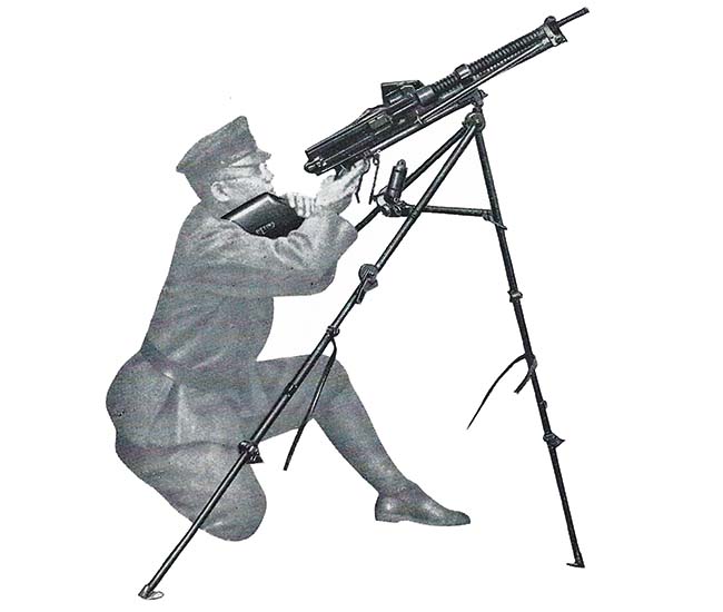
The weapon has a bipod fixed permanently to the gun near the muzzle that can be folded rearward back along the gas tube and barrel when in transport. It can also be fired from the model M1922 folding tripod mount, which is carried by the gun squad for use as desired. When the mount is used the bipod is folded back along the barrel. This mount has both a traversing and elevating mechanism. When the gun is to be used against aircraft, the legs are extended and the tripod raised to its maximum height, which places the gun about four feet from the ground. The elevating device is then unfastened so that the gun will have free traverse and elevation.
Operation
A safety lever located on the left of the trigger guard is shifted downward until approximately vertical for “safe.” In this position its lower end engages a small notch in the side of the trigger guard and cannot easily be displaced. For “fire,” the safety lever is rotated backward and upward until it points horizontally to the rear.
The safety lever is attached to the end of a pin, part of which is cut away. When the safety lever is set at “safe,” the solid portion of the pin obstructs the trigger, whereas when it is set on “fire,” the cutaway allows the trigger to operate freely and to depress the sear.
Before firing, one must be sure that the oil in the oil reservoir is adequately filled. As the rounds are fed into the gun, they work against an oil pump. This allows a small amount of oil to come down on the cartridge, thus oiling the rounds as they are fed into the gun. The ammunition is oiled as this gun does not have a slow initial extraction to prevent ruptured cartridges.
The rate of fire is regulated by means of a gas regulator with several openings of different sizes for the passage of gas through the regulator until it strikes the gas piston. The gas cylinder has five holes of different sizes and is numbered 10 – 15 – 18 – 20 – 28, the small number being the small hole. These holes regulate the force with which the bolt recoils. Adjustments are made to ‘smooth out’ the action of the gun so that only enough gas is utilized to force the recoiling parts to the rear smoothly and without their striking the buffer with excessive force. After initial regulation, changes are necessary only when the gun becomes excessively fouled and dirty, so that more force is required to drive the parts rearward. If the bolt recoils too fast, a smaller hole should be used. If the bolt recoil is slow, sluggish or insufficient, a larger hole should be used.
The ammunition hopper must be filled and is accomplished by raising the follower and placing six five-round clips in the hopper. The follower is then lowered on the cartridges. As the follower is under spring tension it holds the cartridges down against the feed mechanism in the bottom of the hopper.
Cock the gun by pulling back the bolt slide (operating handle) on the left until the projection on the piston engages the sear notch. Push the operating handle forward until its catch clips into the receiver. The gun is now cocked and ready to be fired.
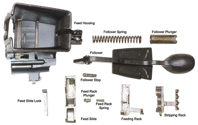
As the bolt is pulled to the rear the operating slide cams the feed slide to the right. As the feed rack plunger is against a shoulder of the feed housing, it causes the feed rack, due to a diagonal cut in the feed slide, to be cammed up until the feed rack plunger (which also raises), comes to a cut-away portion of the feed housing. During this movement the feed racks raise and engage the cartridge in the lower clip. As the feed rack plunger has raised to the cut-away portion of the feed housing it allows the feed and stripping racks to move in with the feed slide, stripping a round from the lower clip and placing it in front of the holding pawl. At the same time the feed rack plunger is cammed in and comes out in another slot.

As the bolt comes forward and pushes the round into the chamber, the feed slide is cammed out. As the feed rack plunger is in another slot the feed racks are held, due to the diagonal cut in the feed slide. The racks are cammed down until the feed rack plunger is cammed in. During this action the feeding and stripping racks have dropped down below the level of the cartridge. After the feed rack plunger has been cammed in, the feeding and stripping racks move out with the feed slide until they reach their outmost position; at that time the feed rack plunger comes out into the first slot and the cycle is repeated. After the cartridge has been stripped from the clip, the clip is ejected out the rear bottom of the hopper by the clip ejector.
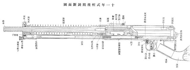
The holding pawl is holding the first round of ammunition in line with the chamber. As the trigger is pulled it causes the sear to move down, disengaging the sear from the operating slide. The operating slide, bolt lock and bolt travel forward under the pressure of the compressed recoil spring, the bolt chambering a round. After the bolt has reached its forward position, the operating slide continues to move forward. As it travels forward it cams the bolt lock down behind the locking lugs on the side of the receiver, locking the breech. As the operating slide continues to move forward, a portion of the operating slide strikes the firing pin, driving it forward, striking the primer and firing the gun.
As the projectile passes the port in the barrel the gases pass down through the port and into the gas cylinder, giving the gas piston a push to the rear. As the gas piston is made on the forward end of the operating slide, the slide also moves to the rear. The first one-half inch of movement cams the bolt lock up, unlocking the bolt. During this movement the bolt lock cams the firing pin back from the face of the bolt. After the bolt is unlocked the operating slide, bolt lock, bolt and empty cartridge case, which is held to the face of the bolt by the extractor, recoil. When these parts have recoiled a sufficient distance, the rear of the bolt strikes the ejector, pushing out on the rear end of the ejector, causing the front end to pivot in knocking the empty cartridge out through the ejection port opening. The operating slide, bolt lock and bolt continue on to the rear, compressing the recoil spring until the bolt strikes the buffer fork, thus absorbing the remainder of the recoil force.
The front and rear sights are of necessity offset to the right to prevent obstruction of sighting by the oil reservoir. To set the rear sight, press the knurled catch on the left side of the rear-sight slide, move the slide to the desired range, and release the catch. The rear sight is in increments ranging from 300 to 1,500 meters. There is no means for windage adjustment.
To unload the weapon, pull back on the knurled feed-housing lock on the feed-house assembly, where it projects out of the lower center of the right side of the feedway, and remove the entire feed-housing hopper assembly to the left. Remove the live ammunition from the feed well of the feed-housing hopper assembly and replace the feed-housing assembly in place on the gun. Do not attempt to unload the gun by working live rounds through the gun, because it fires from an open bolt and will fire when the bolt closes and locks.

Disassembly
Always make sure the weapon is unloaded by visually checking the hopper magazine, feed-housing assembly and the chamber.
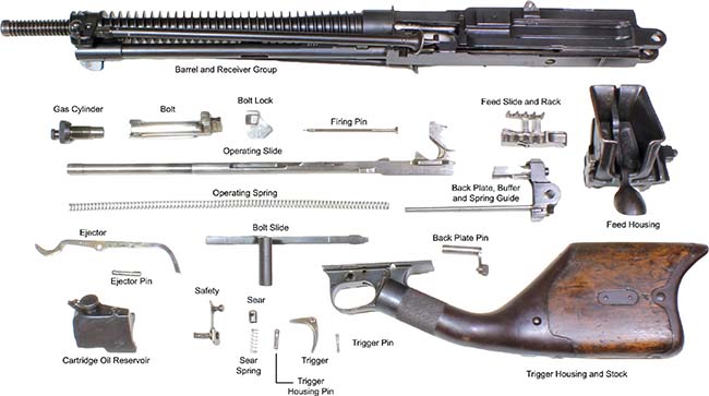
Taking care that the backplate does not fly out under spring tension, remove the backplate pin by releasing the catch, turning it down to a vertical position, and puling it out. Remove the backplate group and operating spring.

Pull the bolt slide (cocking handle) to the rear and remove the operating slide, the bolt, and the bolt lock. Line up the lugs on the bolt slide with the opening on the side of the receiver and remove the bolt slide to the left. Lift the bolt and bolt lock from the operating slide. Slide the firing pin from the rear of the bolt and remove the bolt lock from the bolt by sliding off the top of the bolt. Lift up on the front of the extractor spring and rotate it to the left ninety degrees, and remove from the bolt. The extractor will now lift off of the bolt.
To remove the feed housing from the receiver, pull the feed housing lock, on the front right side of the receiver, to the rear. Slide the feed housing to the left, removing it from the receiver. Note that the feed housing can be removed in the same manner when the gun is assembled and the bolt is in battery position. To further strip the feed mechanism, raise up on the feed slide lock on the rear left side of the feed housing. Slide the feed mechanism to the left, removing it from the feed housing. Slide the stripping and feeding rack to the left and lift up on the stripping rack, separating the two pieces. Press in on the feed rack plunger and lift up on the feed rack, removing it from the feed rack. Extreme care should be used in removing the follower spring. Remove the follower stop, which is located to the rear of the follower pivot. Then raise the follower up, holding the front of the feed housing against a table or some other object to catch the follower plunger and spring. The follower can then be removed by aligning the lugs on the follower pivot with the cut-away portion of the follower bearing on the feed housing. The holding pawl should not be removed except in case of breakage. It is then drifted out to the left.

The oiler assembly is removed by pressing down on the oiler lock, which is located directly in front of the rear sight, and sliding the oiler assembly to the left, removing it from the receiver.
The trigger housing and stock can be removed from the receiver by using a drift to drive out the trigger-housing split pin from right to left. This pin is located between the trigger housing and receiver, directly behind the trigger. By pulling the trigger, the trigger housing together with the shoulder stock can now be removed by sliding it off to the rear of the receiver. To further strip the trigger housing, rotate the safety down, raising up on the end of the safety at the same time, and continue rotation until it is in the forward position, then pull out, removing the safety from the trigger housing. Drift the trigger pin out, removing the trigger, sear and sear spring.
The barrel jacket can be detached by removing the barrel jacket lock retainer plate, which is located on the left rear part of the gas piston tube, by drifting to the front of the weapon. The barrel jacket lock retainer can be removed and the barrel jacket lock drifted to the front of the gun, removing it. The barrel jacket will now unscrew from the receiver, right hand threads.
Unscrew the gas cylinder from the front of the gas piston tube. Slide the gas piston tube to the rear about one inch and remove from the bottom of the barrel jacket. The barrel is pressed into the barrel jacket and cannot be replaced without having access to a press.
The ejector is located on the left top corner of the receiver, and it removed by removing the ejector pin. The bolt locks are located under a plate and are pressed into the receiver, on the right and left side of the receiver, directly behind the feed opening.

Accessories
The Type 11 light machine gun was intended for both infantry and cavalry use. Among the accessories of this weapon are manuals, a small armor shield, foldable tripod, waist ammunition pouch, spare barrel, spare barrel cover, spare feed-housing (hopper) pouch, bulk ammunition sacks, muzzle cap, canvas and leather transport case, spare parts and tools maintenance kit and steel ammunition box containing 24 five-round strips for a total of 120 rounds. There were also special pack and saddle outfits for use by the cavalry.

Conclusion
The Japanese Type 11 (1922) light machine gun was an early attempt at a single man-portable automatic weapon following in the footsteps of the Lewis gun, Chauchat and Hotchkiss Portative. Using the French Hotchkiss as a starting point, tweaking the operating system and adding a unique feed mechanism and a bent buttstock, Colonel Kijiro Nambu made his mark on this early design. Though light and man-portable, its unique feed system was a central cause of its problems in various sandy or muddy environments that Japan fought in and having to oil the cartridges prior to chambering was a big drawback both operationally and logistically. Nevertheless, the gun, when properly maintained, was accurate and reliable and provided the cover for advancing infantry that it was designed for and saw extensive use in Manchuria and China prior to World War II. Although in the 1930s, in skirmishes with the Chinese, the Japanese army realized that their awkward, hopper-fed Type 11 was inferior to the Czech ZB machine guns used by the Chinese and set about to create a similar type of weapon that became the Type 96 and Type 99. With approximately 29,000 Type 11s manufactured from 1922 to 1941, and superseded by the likes of the Type 96 and Type 99 light machine guns, it was never declared obsolete and fought alongside the newer types throughout the entire Pacific Campaign right up to the end of the war. It is believed that four or five companies manufactured the Type 11. Initial production began at the Nagoya Army Arsenal and the Kokura Army Arsenal. TG&E (Tokyo Gas and Electric) produced the Type 11 until production was taken over by the Hitachi Manufacturing Company in 1939. It is possible that the Hoten Arsenal in Manchuria also produced the gun in quantity.
Like many Hotchkiss designs, the Type 11 feels clumsy except when actually fired as its forward center of gravity becomes an advantage. And, since so many of the Hotchkiss designs used feed strips, it was felt the hopper design eliminated snagging problems. Though not a bad idea, it did not meet practical expectations in the field.

The contents of the tool and spare parts wallet are as follows:
1) Brown cowhide leather wallet with stitched in loops and tool holders.
2) White metal cartridge case remover with claw end.
3) Punches (2), one 0.077 in. (2 mm) and one 0.188 in. (4.5 mm).
4) Ruptured case extractor tool.
5) Unidentified tool (not in manual).
6) Standard folding type screwdriver.
7) Gas regulator adjustment tool. One end is to remove, install and adjust the gas cylinder. The other end is to extract a broken firing pin.
8) Scraper attached to end of cleaning rod segment.
9) Cleaning bore rods (2).
10) Operating spring. 16 3/4 in. long x .38 in.
11) Brass drift or cheater bar.
12) Brass hammer with 2 oz. head with wood handle.
13) Spare parts can (tinned steel). The can is 6 in. long (15.24 cm) and 1 in. (25.4 mm) wide. Note that the can is made up of two sections indicated by a raised rib that can be seen on the outer tube with a steel disk in the interior at the point of the rib that provides a partition. The left hand side of the container as shown here is 4 3/4 in. long (12.065 cm) and the right hand side is 1 1/4 in. long (3.175 cm). The following list of items numbered 16-18 fit in the long left hand side of the tube and items numbered 19-28 fit in the smaller right hand side of the tube.
14) Screw cap for left side of spare parts can.
15) Screw cap for right side of spare parts can.
16) Firing pins (2).
17) Extractor springs (3).
18) Bolt spring.
19) Extractors (3).
20) Threaded brass tube for attaching to bore rods to attach cleaning jag. It is 1 in. (26 mm) long and 0.23 in. (6 mm) in diameter with different internal threads on each end: 0.12 in. (3.2 mm) one side, 0.144 in. (3.6 mm) on opposite end.
21) Feed rack plunger.
22) Feed housing follower stop.
23) Coil spring 29 x 9.5 mm (trigger sear spring)
24) Coil Spring 14 x 7.5 mm (back plate buffer spring)
25) Coil Spring 8 x 3 mm (gas regulator adjustment spring)
26) Coil Spring 15 x 4.4 mm (feed rack plunger spring)
27) Coil Spring 20 x 4.3 mm (undetermined)
28) Coil Spring 28 x 4.4mm (oil reservoir applicator spring)
Japanese Type 11 (1922) Light Machine Gun
Weight of gun: 11.5 lbs.
Length of gun: 43.5 inches
Length of barrel: 19 inches
Caliber: 6.5mm (.256 in.)
Ammunition: Model 38 (1905) semi rimmed, reduced-charge cartridges in 5-round clips
Rifling: 4 lands, right hand twist
Sights, front: Inverted V blade with guards, offset to right
Sights, rear: Leaf with open V notch sliding on ramp, graduated from 300 to 1,500 meters, offset to right; no windage adjustment
Operation: Gas-operated, full automatic only
Type of feed: Hopper
Hopper capacity: 30 rounds in six stripper clips
Cyclic rate of fire: 5-600 rounds per minute
Effective rate of fire: 150 rounds per minute.
Production: Approx. 29,000 (1922-1941)
Manufacturer: Nagoya Army Arsenal, Kokura Army Arsenal, Tokyo Gas and Electric (TG&E), Hitachi Heiki and possibly Hoten Arsenal in Manchuria.
